Epipolar Geometry and Image Rectification
Epipolar Geometry & Image Rectification
Multi-View Geometry 에 대해 공부하고 싶다면 아래 블로그 글 쭉 읽어보는 것 추천!!
DarkProgrammerBlog
Epipolar Geometry
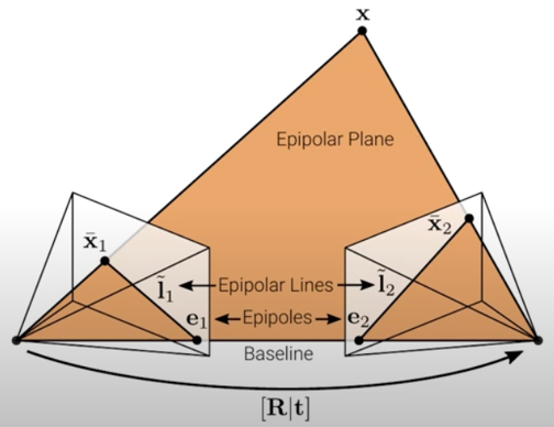
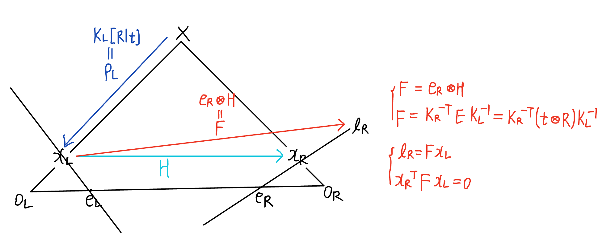
image plane / epipolar plane / baseline / epipole / epipolar line
X : 3D point
\(x_L, x_R\) : projected 2D point in left and right image
파란색 면 : image plane
초록색 면 : epipolar plane
\(O_L, O_R\) : center of left and right camera
직선 \(O_L O_R\) : baseline
epipolar pencil : set of epipolar planes
epipole : intersection of baseline and image plane
\(e_L, e_R\) : epipole of left and right camera
epipolar line :
- intersection of image plane and epipolar plane
- 빨간 선 \(l_R\) : 직선 \(x_R e_R\) (projected 2D point와 epipole은 epipolar line 위에 있다)
- left image plane 위의 같은 점 \(x_L\)로 project 되는 모든 3D points \(X, X_1, X_2, \cdots\)를 right image plane에 project했을 때 그려지는 선
normalized coordinates, pixel coordinates / intrinsic, extrinsic parameters / homography matrix / projection matrix
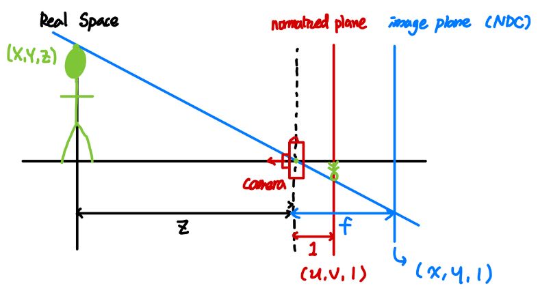
real-world의 3D 좌표 \((X, Y, Z)\) 에 있는 물체를 카메라에 투영하기 위해 Z (= 깊이) 값을 1로 정규화한 평면을 normalized plane이라 하고, \((\frac{X}{Z}, \frac{Y}{Z}, 1)\)의 좌표값을 갖는다.
이를 image로서 나타내기 위해 초점거리를 곱해주고 원점을 정중앙에서 좌상단으로 바꿔서 normalized plane 상의 normalized coordinates \((\frac{X}{Z}, \frac{Y}{Z}, 1)\)을 image plane 상의 pixel coordinates \((\frac{X}{Z} \ast f_x + \frac{W}{2}, \frac{Y}{Z} \ast f_y + \frac{H}{2}, 1)\) 로 변환할 수 있는데,
이 때 곱하게 되는 행렬이 바로 intrinsic matrix (= calibration matrix) K 이다. 그리고 이렇게 intrinsic parameters를 구하는 과정을 Camera Calibration 이라 부른다.
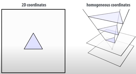
한편, normalized coordinate \(p = (x, y, 1)\)에 대해
any \(\hat p = (X, Y, Z)\) where \((\frac{X}{Z}, \frac{Y}{Z}) = (x, y)\)처럼
single matrix (translate, rotate, and scale)로 같아질 수 있는 coordinates를
homogeneous coordinates for \(p\) 라고 부른다.
그런데, 카메라의 각도 혹은 위치가 달라지면 맺히는 이미지 자체도 달라지기 때문에 intrinsic matrix를 곱하기 전에 camera의 rotation 및 translation을 먼저 고려해주어야 하는데, 이 때 곱하게 되는 행렬이 바로 extrinsic marix \([R \vert t]\) 이다.
-
K : intrinsic parameters(3x3calibrationmatrix) (초점거리 곱하고 원점 바꾸는 등 pixel-coordinate에 projection하기 위한 카메라 자체의 특성) -
R, t : extrinsic parameters(3x3rotation, 3x1translationmatrix) (두 카메라의 상대적인 pose(위치 및 각도))
즉, 정리하면 3D point [X, Y, Z]가 image plane [x, y]에 맺히는 projection 과정은 아래의 수식을 따른다.
\(\begin{bmatrix} x \\ y \\ z \end{bmatrix}\) = \(\begin{bmatrix} f_x & s & W/2 \\ 0 & f_y & H/2 \\ 0 & 0 & 1 \end{bmatrix}\) \([R \vert t]\) \(\begin{bmatrix} X \\ Y \\ Z \\ 1 \end{bmatrix}\)
\(s\) : skew due to sensor not mounted perpendicular to the optical axis
- \(x_L \Leftrightarrow x_R\) : homography matrix H (projection of 2D point to 2D point)
\(x_R = H x_L\) - \(X \Leftrightarrow x_L\) : projection matrix \(P_L\) (projection of 3D point to 2D point)
\(x_L = P_LX\) where \(P_L = K_L[R \vert t]\)
Fundamental matrix
우선 \(\circledast\) 로 외적을 표시하자.
- \[x_R = H x_L\]
- \(e_R\)과 \(x_R\)은 직선 \(l_R\) 위에 있으므로 \(e_{R}^{T} l_R = 0\) and \(x_{R}^{T} l_R = 0\)
예를 들어, 직선 2x+y-2z = 0에 대해 \(l_R\)은 (2, 1, -2)이고, \(e_R\) 및 \(x_R\)은 직선 위에 있는 점 (x, y, z)이다. - 위의 1.과 2.로부터 \(l_R = e_R \circledast x_R = e_R \circledast H x_L = F x_L\)
where F = fundamental matrix = \(e_R \circledast H\) - 위의 2.와 3.으로부터 \(x_{R}^{T} l_R = x_{R}^{T} F x_L = 0\)
- 위의 2.와 3.으로부터 \(e_{R}^{T} l_R = e_{R}^{T} F x_L = 0\) 이고, 모든 \(x_L\)에 대해 \(e_{R}^{T} F = 0\)을 만족하므로 \(e_R\)은 F의 left null vector이다. (유사한 방법으로 \(e_L\)은 F의 right null vector이다.)
즉, fundamental matrix와 관련된 식을 정리하면
-
fundamental matrix: \(F = e_R \circledast H\) -
correspondence condition: \(x_{R}^{T} F x_L = 0\) -
epipolar line: \(l_R = F x_L\) -
epipole: \(e_{R}^{T} F = 0\) (\(e_R\)은 F의 left null vector)
Essential matrix
essential matrix는 fundamental matrix의 specialization으로, pixel coordinates이 특별히 calibrated camera들을 다루는 normalized image coordinates (K = I)인 경우에 사용된다. 즉, K = I 여서 \(x^{\ast} = PX = K[R \vert t]X = [R \vert t]X\) 를 만족하는 \(x^{\ast}\)을 normalized coordinates에 있는 image point라 부른다.
그리고 epipolar constraint란, vector \(x_L O_L\)과 vector \(x_R O_R\)과 vector \(O_L O_R\)이 같은 평면 epipolar plane 위에 있다는 것이다. 이를 normalized coordinates에서 생각하면, \(x_R^{\ast}\)과 \(Rx_L^{\ast}\)과 t가 같은 평면 epipolar plane 위에 있다는 뜻이므로 (그 이유는 아래의 Algebraic derivation을 참고하자) 이를 간단하게 수식으로 표현하면 \(x_R^{\ast T}(t \circledast Rx_L^{\ast}) = 0\) 이다.
즉, essential matrix와 관련된 식을 정리하면
-
essential matrix: \(E = t \circledast R\) -
correspondence condition: \(x_R^{\ast T} E x_L^{\ast} = 0\) - 특징 : 3 \(\times\) 3 matrix, rank = 2, null space = 1
Relationship between fundamental matrix and essential matrix
이제 intrinsic parameters인 calibration matrix K를 이용하여 uncalibrated camera들을 다루는 general case로 확장해보자. \(x_L^{\ast}\) 이 normalized coordinates에서의 image point였고, \(x_L\)은 일반적인 pixel coordinates에서의 image point라고 할 때,
- \(x_L = K_L x_L^{\ast}\) 이고, \(x_R = K_R x_R^{\ast}\) 이므로 \(x_L^{\ast} = K_L^{-1}x_L\) 이고, \(x_R^{\ast} = K_R^{-1}x_R\)
- \[x_R^{\ast T} E x_L^{\ast} = 0\]
- 위의 1.과 2.로부터 \(x_R^{T} (K_R^{-T} E K_L{-1}) x_L = 0\)
이 때, 위의 3.은 \(x_{R}^{T} F x_L = 0\) 꼴과 같으므로
즉, fundamental matrix와 essential matrix 간의 관계식을 정리하면
-
fundamental matrix: \(F = e_R \circledast H\) -
essential matrix: \(E = t \circledast R\) -
relationshiop: \(F = K_R^{-T} E K_L^{-1} = K_R^{-T} t \circledast R K_L^{-1}\)
(F는 \(K_L, K_R, R, t\) 만으로 표현 가능)
즉, fundamental matrix F는 각 camera의 calibration matrix \(K_L, K_R\)과 두 camera 사이의 상대적인 rotation R 및 translation t에 의존한다는 것을 알 수 있다.
Algebraic derivation
\(F = K_R^{-T} E K_L^{-1} = K_R^{-T} t \circledast R K_L^{-1}\) 임을 조금 더 수학적으로 유도해보자.
상대적인 카메라의 위치인 extrinsic parameters의 경우 left camera에 world origin이 있다고 가정하여 이에 대해 상대적인 right camera의 위치를 R, t로 지정하자.
\(ax_L = K_L[I \vert 0]X\)
\(bx_R = K_R[R \vert t]X\)
(여기서 a, b는 단순히 scale factor)
\(X = [x, y, z, 1]^T = [X^{\ast}, 1]^T\) 에 대해
\(ax_L = K_{L}X^{\ast}\)
\(bx_R = K_{R}(RX^{\ast}+t)\)
\(X^{\ast} = aK_{L}^{-1}x_L\)을 \(bK_{R}^{-1}x_R = RX^{\ast}+t\)에 대입하면,
- \(bK_{R}^{-1}x_R = aRK_{L}^{-1}x_L + t\)
이 때, vector \(bK_{R}^{-1}x_R\)은 vector \(aRK_{L}^{-1}x_L\)와 vector \(t\)의 합이므로 기하학적으로 \(bK_{R}^{-1}x_R\)과 \(aRK_{L}^{-1}x_L\)과 \(t\)는같은 평면 위에 있다. (그리고 그 평면은 epipolar plane이다.)
따라서 vector \(v = t \circledast RK_{L}^{-1}x_L\) 는 epipolar plane에 수직이므로 \(bK_{R}^{-1}x_R\)와 \(v\)의 내적은 0이다.
\(b(K_{R}^{-1}x_R)^{T}v = a(RK_{L}^{-1}x_L)^{T}v + t^{T}v = 0\) 이라 쓸 수 있다.
\(b(K_R^{-1}x_R)^{T}v = 0\)에 \(v = t \circledast RK_{L}^{-1}x_L\) 를 대입하면 \(x_R^{T} (K_R^{-T} (t \circledast R) K_L^{-1}) x_L = 0\) 이다. - \(bx_R = aK_{R}RK_L^{-1}x_L + K_{R}t\)
이와 비슷하게 vector \(w = K_{R}t \circledast K_{R}RK_{L}^{-1}x_L\)는 \(bx_R = aK_{R}RK_{L}^{-1}x_L + K_{R}t\) 에 수직이므로 \(bx_{R}^{T}w = a(K_{R}RK_{L}^{-1}x_L)^{T}w + (K_{R}t)^{T}w = 0\) 이라 쓸 수 있다.
\(bx_{R}^{T}w = 0\)에 \(w = K_{R}t \circledast K_{R}RK_{L}^{-1}x_L\) 를 대입하면 \(x_{R}^{T} (K_{R} t \circledast K_{R}RK_{L}^{-1}) x_L = 0\) 이다. - 위의 1., 2.에서 유도한 \(x_R^{T} (K_R^{-T} (t \circledast R) K_L^{-1}) x_L = 0\)과 \(x_{R}^{T} (K_{R} t \circledast K_{R}RK_{L}^{-1}) x_L = 0\)을 통해
\(F = K_{R}^{-T} t \circledast R K_{L}^{-1}\) 임을 유도할 수 있다.
(F 유도에 \(x_{R}^{T} (K_{R} t \circledast K_{R}RK_{L}^{-1}) x_L = 0\) 은 왜 필요한 거지..?????? 조금 더 공부 필요)
Image Rectification
Image rectification은 주어진 images를 common image plane에 project하는 것이다. 여러 각도에서 찍은 이미지들 간에 매칭되는 점들을 쉽게 찾기 위해 computer stereo vision 분야에서 널리 사용되는 transform 기법이다. 이 때, 매칭되는 점들을 찾는 것은 위에서 설명한 epipolar geometry에 의해 수행된다.
(epipolar geometry 요약 : 한 image의 어떤 pixel에 매칭되는 3D 상의 점들은 다른 image의 epipolar line 위에 있다.)
parallel stereo cameras : e.g. 두 카메라 사이의 관계가 t = [T; 0; 0] (shifted in x-direction)
만약 두 image plane이 같은 평면 상에 있다면 optical axes가 parallel하여모든 epipolar line은 horizontal axis에 평행하고 epipoles는 infinite point in [1, 0, 0]T direction in homogeneous coordinates로 mapping되며, 매칭되는 점들이 같은 vertical coordinates를 가진다.그리고 이 때 매칭되는 점들을 찾는 것은 matching cost(minimize SSD or maximize normalized correlation)를 찾기 위해 horizontal scan만 하면 되므로 쉬운 문제이다.
예를 들어, left image의 어떤 pixel (\(x_l, y_l\))에 대응되는 점을 right image에서 찾는다고 가정하자. 이 때, right image에서의 horizontal scan이 \(x_l\) 의 위치(아래 오른쪽 사진의 빨간 점)을 넘어가서는 안 된다. right image에서 \(x_l\) 의 오른쪽에 matching point가 있다면 연장선을 그었을 때 3D point가 camera center의 뒤쪽에 있다는 것을 의미하기 때문이다.
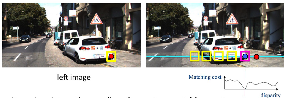
그런데 horizontal scan을 하며 모든 pixel에 대해 matching cost를 일일이 찾는 건 inefficient하므로 positive matches & negative matches 만들어서 classifier training 할 수 있다.
(smaller patch size : more detail, but noisy)
(bigger patch size : less detail, but smooth)
이를 통해 disparity map을 얻을 수 있고, depth map을 얻을 수 있다.
For post-processing, MRF(Markov Random Field) or CRF(Conditional Random Field) : energy minimization
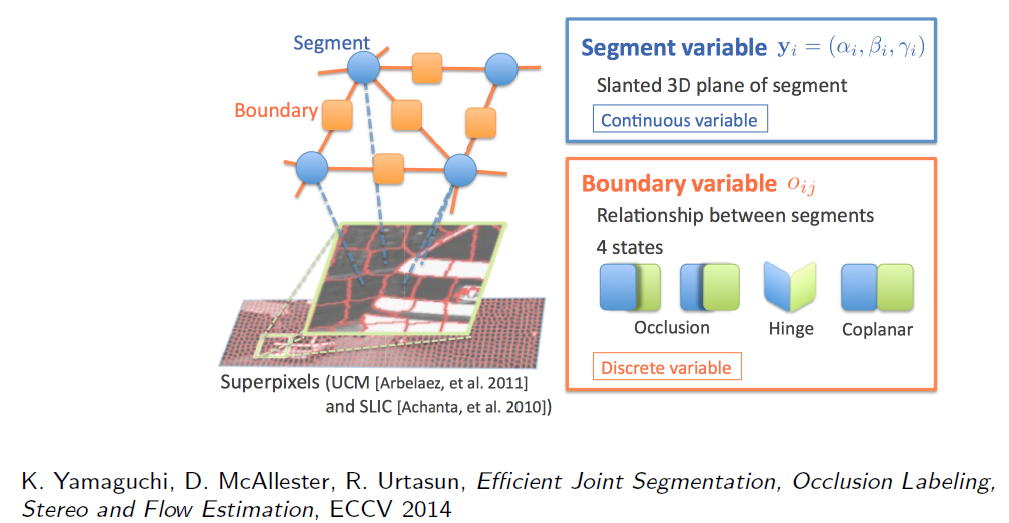

general stereo cameras : 두 카메라 사이의 관계가 [R|t]
하지만, 두 카메라는 보통 서로 rotate, translate 되어 있기 때문에두 image를 warp해서라도 두 image plane이 같은 평면 상에 있던 것처럼 (모든 epipolar line이 수평선이 되도록) 만들 필요가 있고, 이것이 바로 image rectification이다.
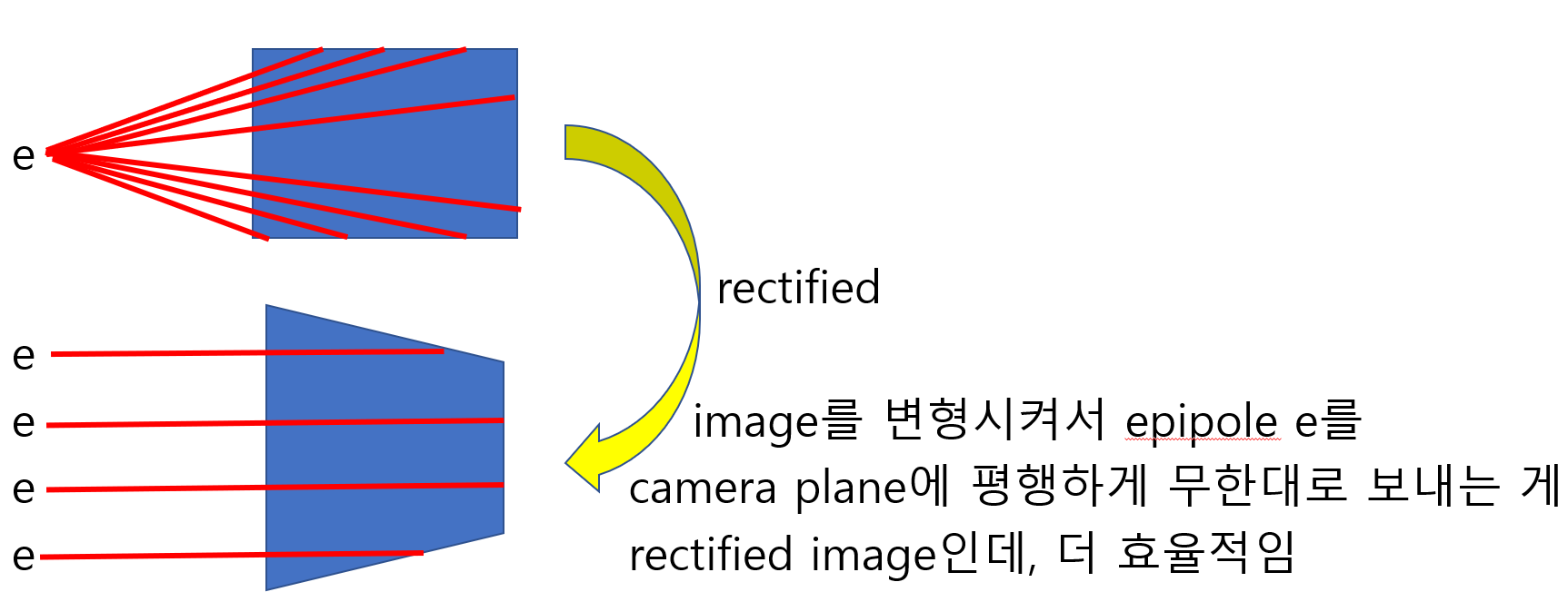
Image rectification은 두 images에 대해 동시에 수행되며, 일반적으로 셋 이상의 images에 대해서는 simultaneous rectification이 불가능하다.
calibrated cameras에 대해서는 essential matrix가 두 camera 사이의 관계를 설명(\(x_{R}^{\ast T} E x_{L}^{\ast} = 0\))하고, uncalibrated cameras (general case)에 대해서는 fundamental matrix가 두 camera 사이의 관계를 설명(\(x_{R}^{T} F x_L = 0\))한다.
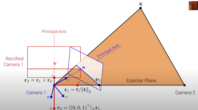
파란색 axis : camera coordinate
빨간색 axis : rectified camera coordinate
rectified camera coordinate \(r_{1}, r_{2}, r_{3}\) 구하는 방법 :
\(r_{1} = \frac{t}{\| t \|}\) where \(t\) is vector from camera 1 to camera 2
\(r_{2} = \begin{bmatrix} 0 \\ 0 \\ 1 \end{bmatrix} \times r_{1}\) where \(\begin{bmatrix} 0 \\ 0 \\ 1 \end{bmatrix}\) is z-axis from original camera coordinate
\(r_{3} = r_{1} \times r_{2}\)
Image rectification 알고리즘은 대표적으로 세 가지가 있다. : planar, cylindrical, and polar rectification
Image rectification을 수행하기 위해서는 projective transformation을 위해 homography matrix \(H_L, H_R\)를 찾아야 하는데, 여러 방법 중 하나를 아래에서 소개하겠다.
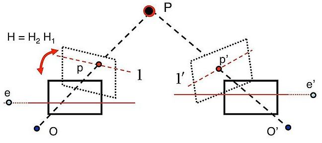
우선 left camera에 world origin이 있다고 가정하여 이에 대해 상대적인 right camera의 위치를 R, t로 지정하자.
right-camera-coordinate에서의 점 \(X_R\) 을 left-camera-coordinate (world-coordinate)에서 나타내려면 \([R \vert t] X_R = R X_{R} + t\) 이고,
반대로 left-camera-coordinate (world-coordinate) 에서의 점 \(X_L\)을 right-camera-coordinate에서 나타내려면 \(R^{T}(X_{L} - t)\) 이다.
따라서 left-camera-coordinate (world-coordinate) 에서의 world origin \(O_{L} = 0\)을 right-camera-coordinate에서 나타내려면 \(R^{T}(0 - t) = -R^{T} t\) 이다.
따라서 \(O_{L} = 0, O_{R} = -R^{T} t\) 라 쓸 수 있고,
3D 상의 점 \(X_{L}, X_{R}\)을 2D 상의 점 \(x_{L}, x_{R}\)으로 project시키는
projection matrix는 \(P_{L} = K_{L}[I \vert 0], P_{R} = K_{R}[R \vert t]\) 라 쓸 수 있다.
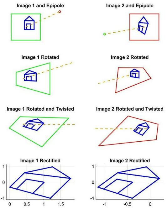
- 첫 번째로,
epipole의 위치를 구한다.
\(O_R\)을 left image plane에 project한 게 \(e_L\) 이고, \(O_L\)을 right image plane에 project한 게 \(e_R\) 이므로
\(e_{L} = P_{L} [O_{R} ; 1] = P_{L} [-R^{t} t ; 1] = K_{L}[I \vert 0][-R^{t} t ; 1] = - K_{L} R^{t} t\)
\(e_{R} = P_{R} [O_{L} ; 1] = P_{R} [0 ; 1] = K_{R}[R \vert t][0 ; 1] = K_{R} t\) - 두 번째로,
left image plane이 baseline에 평행해지도록 rotate시키는 projective transformation HL1 을 구한다. 이는 original optical axis와 desired optical axis 간의 외적으로 구할 수 있다. - 세 번째로,
horizontal axis가 baseline 및 epipolar line과 평행해지도록 twist시키는 projective transformation\(H_{L2}\) 를 구한다. 맞게 구했다면 twist 후 epipoles가 infinity in x-direction로 mapping되어야 한다. - 네 번째로, left image를 rectify하는
최종 projective transformation\(H_{L} = H_{L2}H_{L1}\) 을 구한다. - 다섯 번째로, 같은 방법으로 right image를 rectify하는
최종 projective transformation\(H_{R} = H_{R2}H_{R1}\)을 구한다. 여기서 주의할 점은, left image와 right image를 각각 \(H_{L1}\)과 \(H_{R1}\)으로rotate한 후에 optical axis가 서로 평행해야 한다.
One strategy is to pick a plane parallel to the line where the two original optical axes intersect to minimize distortion from the reprojection process. 또는 We simply define as \(H_{R} = H_{L} R^{t}\)
(?????) - 마지막으로, two images가 same resolution을 갖도록
scale해준다. 그러면 horizontal epipoles가 align되어 매칭되는 점들이같은 vertical coordinates를 가지므로 매칭되는 점들을 찾기 위해horizontal scan만 하면 되는 쉬운 문제로 바뀐다. -
Eight-Point Algorithm:- 꼭 \(K_{L}, K_{R}\)
intrinsic parameter를 모르더라도
두 images 사이의 8 corresponding points만 알면
fundamental matrix와 epipoles를 계산할 수 있어서
image rectification을 수행할 수 있다! - fundamental matrix \(F\)는 3-by-3 matrix이므로 미지수가 9개인데
\(x_{R}^{T} F x_L = 0\) 에서 \(x_L, x_R\) pair 8개를 알고 있다면
8개의 연립방정식의 해를 구해서 \(F\) 를 계산할 수 있다
9개의 미지수를 가진 8개의 연립방정식의 해의 경우
SVD(Singular Value Decomposition)으로 근사값을 찾을 수 있다
추가로, \(x_L, x_R\) 을 normalize하면 근사값의 오차를 줄일 수 있다
- 꼭 \(K_{L}, K_{R}\)
참고 사이트 :
https://blog.naver.com/hms4913/220043661788
https://en.wikipedia.org/wiki/Image_rectification#cite_note-HARTLEY2003-9
https://csm-kr.tistory.com/64
CSC420: Intro to Image Understanding 수업 내용
중간중간에 있는 물음표들은 아직 이해하지 못해서 남겨놓은 코멘트입니다.
추후에 다시 읽어보고 이해했다면 업데이트할 예정입니다.
혹시 알고 계신 분이 있으면 댓글로 남겨주시면 감사하겠습니다!